Panel - Overview
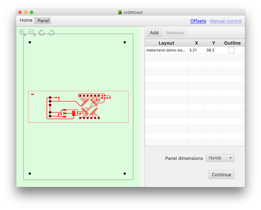
The left side of a panel screen provides a preview of the board locations on the laminate. The right side of a panel screen lists the boards located on the panel and shows the dimension of the panel.
You can use buttons Add and Remove above the table to add a new board to the panel or remove an existing board from the panel. A new board is placed in the center of the panel by default.
Panel layout
When adding a new board, open file dialog lets you select either .cmp (top layer traces) or .sol (bottom layer traces) file. It does not matter which file exactly you select – the application will then attempt to load all supported files, looking for files with extensions corresponding to other layers in the same folder. You can refer to the section Gerber files for more information on the gerber files and their extensions.
Board position on the panel can be changed either by dragging it on the preview pane:

or by specifying the exact coordinates in the table:
Board can be rotated using rotation icons at the top left corner of the preview pane:

Zooming
Zoom icons at the top left corner of preview pane can be used to zoom in and out:
It’s also possible to use keyboard shortcuts for zooming: Ctrl+= (or Cmd+=) to zoom in, or Ctrl+- (Cmd+-) to zoom out
Outline
If board’s design does not include contour milling, it can be automatically generated by clicking on the “Outline” checkbox in the table. This will add contour milling tool path around the perimeter of the board, leaving a perforated tab at the centers.

All changes have immediate effect – no saving is required.
When you are happy with the layout of the panel, click on Continue button takes you to the next stage.